chalkline

Public teaching whiteboard

Raspberry Pi GPIO: LED & I2C hands-on

GPIO LED and I2C on Raspberry Pi — hands-on public tutorial whiteboard. · by zlu

Topics: Raspberry Pi tutorials

Raspberry Pi GPIO: LED & I2C hands-on

Session 03 · GPIO: blink an LED, then talk I2C

Hands-on wiring + copy-paste Python. You will light an LED on GPIO17, scan the I2C bus, and understand which pins are safe to use.

Safety first (read once)

• Power the Pi OFF before changing jumper wires • Pi GPIO is 3.3V logic — do not feed 5V into a GPIO input • Always share GND between Pi and the breadboard circuit • Start with LEDs + resistors before sensors • If something smells hot / ACT LED dies — unplug power immediately

Parts for the LED lab

• Breadboard + jumper wires • 1× LED • 1× 220Ω (or 330Ω) resistor • Pi with 40‑pin header (Zero 2 W with headers, Pi 4/5)

Pin map we will use

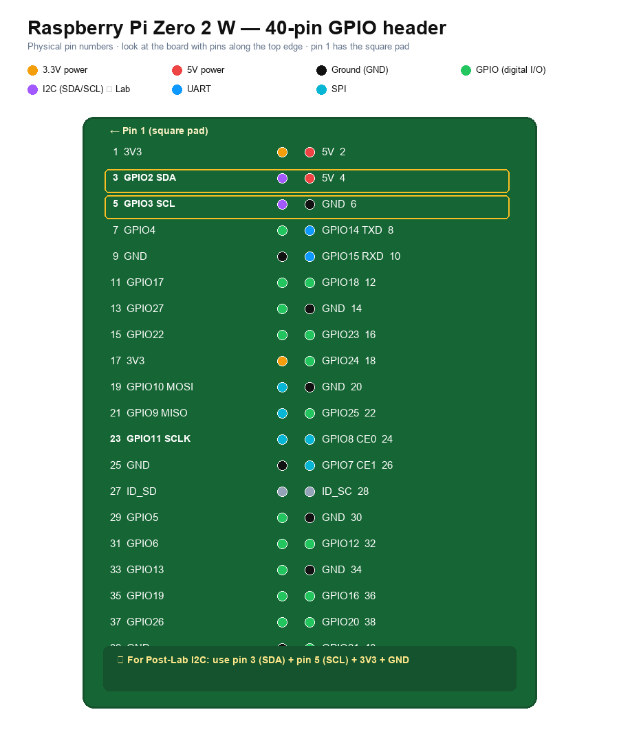
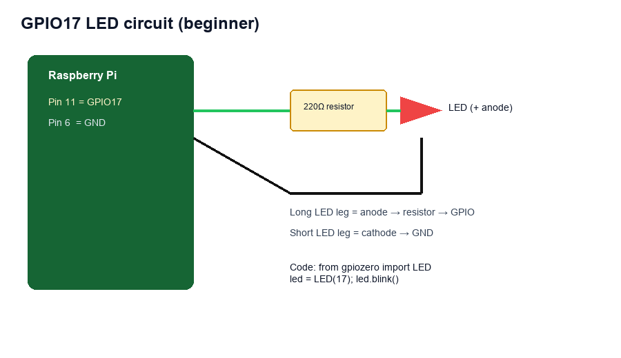
Physical pin 11 → GPIO17 → LED anode path Physical pin 6 → GND → LED cathode Orientation tip: pin 1 is the square pad / usually marked near the corner of the header.

Step 1 — Wire the LED

1. Shutdown: sudo poweroff — wait for LEDs to go dark — unplug power 2. LED long leg (anode) → 220Ω resistor → jumper to physical pin 11 (GPIO17) 3. LED short leg (cathode) → jumper to physical pin 6 (GND) 4. Double-check no bare wires short 5V to GND 5. Power the Pi back on and SSH in

Step 2 — Blink with gpiozero

sudo apt update sudo apt install -y python3-gpiozero nano ~/projects/blink.py from gpiozero import LED from time import sleep led = LED(17) # BCM numbering: GPIO17 print('blinking GPIO17 — Ctrl+C to stop') while True: led.on(); sleep(0.5) led.off(); sleep(0.5) python3 ~/projects/blink.py

Step 3 — Enable I2C (for sensors)

Many sensors (BME280, OLEDs, etc.) use I2C — two wires shared by many chips. sudo raspi-config # Interface Options → I2C → Enable sudo reboot After reboot: sudo apt install -y i2c-tools python3-smbus ls /dev/i2c* sudo i2cdetect -y 1 An empty grid is OK until a sensor is wired. Typical I2C pins on the 40‑pin header: SDA = physical pin 3 (GPIO2) SCL = physical pin 5 (GPIO3) 3.3V = physical pin 1 GND = physical pin 6 or 9

Wire a BME280 (example)

BME280 VIN → 3.3V (pin 1) BME280 GND → GND BME280 SDA → pin 3 BME280 SCL → pin 5 Then i2cdetect should show 0x76 or 0x77.

Read it in Python (outline)

pip install bme280 smbus2 # inside a venv from smbus2 import SMBus from bme280 import BME280 bus = SMBus(1) bme = BME280(i2c_dev=bus) print(bme.get_temperature()) Next upgrade: return that value from a Flask route in Session 02’s webapp.

Checklist

☐ LED blinks on GPIO17 ☐ You can point to physical pins 11 and 6 on the header ☐ I2C enabled; i2cdetect runs ☐ You know SDA/SCL pin numbers Next: Session 04/05 for always‑on services, or 06 to add a camera.

Drag to pan · scroll to zoom · read-only

Board contents

Text extracted from this public whiteboard for search and accessibility.

Raspberry Pi GPIO: LED & I2C hands-on

Session 03 · GPIO: blink an LED, then talk I2C

Hands-on wiring + copy-paste Python. You will light an LED on GPIO17, scan the I2C bus, and understand which pins are safe to use.

Safety first (read once)

• Power the Pi OFF before changing jumper wires • Pi GPIO is 3.3V logic — do not feed 5V into a GPIO input • Always share GND between Pi and the breadboard circuit • Start with LEDs + resistors before sensors • If something smells hot / ACT LED dies — unplug power immediately

Parts for the LED lab

• Breadboard + jumper wires • 1× LED • 1× 220Ω (or 330Ω) resistor • Pi with 40‑pin header (Zero 2 W with headers, Pi 4/5)

Pin map we will use

Physical pin 11 → GPIO17 → LED anode path Physical pin 6 → GND → LED cathode Orientation tip: pin 1 is the square pad / usually marked near the corner of the header.

Step 1 — Wire the LED

1. Shutdown: sudo poweroff — wait for LEDs to go dark — unplug power 2. LED long leg (anode) → 220Ω resistor → jumper to physical pin 11 (GPIO17) 3. LED short leg (cathode) → jumper to physical pin 6 (GND) 4. Double-check no bare wires short 5V to GND 5. Power the Pi back on and SSH in

Step 2 — Blink with gpiozero

sudo apt update sudo apt install -y python3-gpiozero nano ~/projects/blink.py from gpiozero import LED from time import sleep led = LED(17) # BCM numbering: GPIO17 print('blinking GPIO17 — Ctrl+C to stop') while True: led.on(); sleep(0.5) led.off(); sleep(0.5) python3 ~/projects/blink.py

Step 3 — Enable I2C (for sensors)

Many sensors (BME280, OLEDs, etc.) use I2C — two wires shared by many chips. sudo raspi-config # Interface Options → I2C → Enable sudo reboot After reboot: sudo apt install -y i2c-tools python3-smbus ls /dev/i2c* sudo i2cdetect -y 1 An empty grid is OK until a sensor is wired. Typical I2C pins on the 40‑pin header: SDA = physical pin 3 (GPIO2) SCL = physical pin 5 (GPIO3) 3.3V = physical pin 1 GND = physical pin 6 or 9

Wire a BME280 (example)

BME280 VIN → 3.3V (pin 1) BME280 GND → GND BME280 SDA → pin 3 BME280 SCL → pin 5 Then i2cdetect should show 0x76 or 0x77.

Read it in Python (outline)

pip install bme280 smbus2 # inside a venv from smbus2 import SMBus from bme280 import BME280 bus = SMBus(1) bme = BME280(i2c_dev=bus) print(bme.get_temperature()) Next upgrade: return that value from a Flask route in Session 02’s webapp.

Checklist

☐ LED blinks on GPIO17 ☐ You can point to physical pins 11 and 6 on the header ☐ I2C enabled; i2cdetect runs ☐ You know SDA/SCL pin numbers Next: Session 04/05 for always‑on services, or 06 to add a camera.